I wish I had more resources to get a move on with my L200, but they're all being chewed up on either doing routine repairs like timing belts, servicing and trying to off load one daily for another and get it running right. We got mortgages, kids and all of these other distractions stopping us from doing what is importantd3v147 wrote:Apologies. My comment was stupid and clearly incorrect given the response it generated. I can totally appreciate that not everybody can blow bulk time and money on their projects!
Matt's Red GN
Re: Matt's Red GN
I'm pretty sure there are more compact flex joins for exhaust systems. Whatever you do, try to get one welded into the system - I guarantee it'll eventually break something...

Re: Matt's Red GN
Well I didn't get a great deal over the weekend. I had to deal with normal housechores and CNC some 1UZFE flanges for a mate. What I did get done was weld up the exhaust as it was all only tacked, get the mounts in place, weld the o2 bung (I decided not to worry about the EGT sensor for the moment). I also started thinking about my ignition configuration. My plan is to use VN+ commodore coil packs and mount them to the four bolts holes at the front of the motor above the water pump.
I tried to weld a bracket onto the dump to secure it where the factory exhaust is normally attached, but it made it impossible to remove.

Here is a Commodore coilpack based ignition i used on an RB20DET.

I tried to weld a bracket onto the dump to secure it where the factory exhaust is normally attached, but it made it impossible to remove.
Here is a Commodore coilpack based ignition i used on an RB20DET.
Re: Matt's Red GN
I began making a bracket up for the coils. I know it looks close to the manifold but there is ample space for a heat shield to go in between and it should receive plenty of air cooling. If they die they are only commodore coilpacks and I tend to pick them up for 20-30 bucks a set. I was going to use LS1 coils but they cost more and I wouldn't be able to mount them so conveniently.

Re: Matt's Red GN
Intercooler turned up. Looks like it will work out well.

-
astronturbo77
- Sigma-Galant Police (Global Mod)
- Posts: 1356
- Joined: Thu Mar 26, 2009 8:09 pm
- Location: Hobart Tasmania
Re: Matt's Red GN
Have you thought about welding some 90 degree bends on the cooler outlets to make things easier? Ive got a 30 degree 3 inch mandrel bend here if you can use it?
BUILT NOT BROUGHT BY ALGIE.
Re: Matt's Red GN
The bends kind of need to squish a bit to get through the holes that are there with the bumper mounted. I want to avoid cutting the firewall if at all possible. It's all 2.5" so I can't use that bend but cheers anyway.
Re: Matt's Red GN
Looks like I'm going to have to go down this path. I am going to use an aluminium donut, and enlarge the holes around the bumper brackets a tiny bit. I'll also get some button head type or CSK style bolts for the bumper so that they are more compact.astronturbo77 wrote:Have you thought about welding some 90 degree bends on the cooler outlets to make things easier? Ive got a 30 degree 3 inch mandrel bend here if you can use it?
http://www.ebay.com.au/itm/Aluminium-In ... 85a&_uhb=1

I added a heat shield to the coil pack bracket. I think stainless should do a good enough job. I will probably mount an electronic boost solenoid un the underside of this later on too.
I need to get some shorter leads as I'm not sure if you can shorten spiral wound leads yourself.

Re: Matt's Red GN
nice work on here, congrats
what engine management will you run on the engine?
what engine management will you run on the engine?
Re: Matt's Red GN
I'm going to be using a Megasquirt 3. I was going to use a Megasquirt 1 but I don't like it. I think the benefits far outweigh the extra cost.Tomica93 wrote:nice work on here, congrats
what engine management will you run on the engine?
Re: Matt's Red GN
This weekend I went to see my father for his birthday. This resulted in a lot of drinking and I didn't get much done on the car. I did get some little jobs out of the way and I am going to post about them just to keep up the habit.
Firstly, I welded a flex joint in the the zorst. I put it where the old hotdog muffler used to sit as it is the only place with a good amount of space. As it is, the exhaust is probably going to rattle against the body a lot - so I didn't want to make it worse.

I finished bolting the exhaust off to the car and I am not going to touch it again until after the first test drives. I cut off the tailpipe to a nice length and I think it looks innocent enough.

These springs came out of the rear of a VH or VK wagon that had uprated srpings for carrying a load. Hopefully I can cut them up and fit them in the rear and they are a better match for the super heavy duty 4wd shocks installed.

All in one coil driver ICs are lovely. As they switch the negative to the coil i just earthed that leg directly to the mounting plate. All I need is a logic level pulse from the ECU into the resistors and the coils work perfectly (Well one was a dud but I had a spare)

Everything came up quite neatly. I just need to get a decent plug for the module.

I tapped all the extra vacuum ports I needed into random spots on the inlet. I moved the booster one to a better spot and conveniently it was the same thread as the smaller nipples.

I went on a hunt to get the fittings for the master cylinder and the intercooler piping but it is still a waiting game unfortunately. If I don't see these parts tomorrow I think I will begin rewiring the column controls.
Firstly, I welded a flex joint in the the zorst. I put it where the old hotdog muffler used to sit as it is the only place with a good amount of space. As it is, the exhaust is probably going to rattle against the body a lot - so I didn't want to make it worse.
I finished bolting the exhaust off to the car and I am not going to touch it again until after the first test drives. I cut off the tailpipe to a nice length and I think it looks innocent enough.
These springs came out of the rear of a VH or VK wagon that had uprated srpings for carrying a load. Hopefully I can cut them up and fit them in the rear and they are a better match for the super heavy duty 4wd shocks installed.
All in one coil driver ICs are lovely. As they switch the negative to the coil i just earthed that leg directly to the mounting plate. All I need is a logic level pulse from the ECU into the resistors and the coils work perfectly (Well one was a dud but I had a spare)
Everything came up quite neatly. I just need to get a decent plug for the module.
I tapped all the extra vacuum ports I needed into random spots on the inlet. I moved the booster one to a better spot and conveniently it was the same thread as the smaller nipples.
I went on a hunt to get the fittings for the master cylinder and the intercooler piping but it is still a waiting game unfortunately. If I don't see these parts tomorrow I think I will begin rewiring the column controls.
-
Superscan811
- Posts: 1689
- Joined: Sun Mar 22, 2009 4:12 pm
- Location: Sydney
Re: Matt's Red GN
Looking good.
While it's a bit of overkill because it can handle 55Volts and 169Amps, they are designed for automotive use, and are the same 3 pin package. The only thing I don't know is does the ECU do the dwell?
If you need to replace a coil driver, you may be able to use an IRF1405 N-Channel MOSFET (Jaycar part No:ZT2468), which costs around $5. Logic level (5v) switching, and it switches the negative.d3v147 wrote:All in one coil driver ICs are lovely. As they switch the negative to the coil i just earthed that leg directly to the mounting plate. All I need is a logic level pulse from the ECU into the resistors and the coils work perfectly (Well one was a dud but I had a spare)
While it's a bit of overkill because it can handle 55Volts and 169Amps, they are designed for automotive use, and are the same 3 pin package. The only thing I don't know is does the ECU do the dwell?
Have you looked at the MicroSquirt v3? They are relatively cheap and are based on the Megasquirt 3.d3v147 wrote:I'm going to be using a Megasquirt 3. I was going to use a Megasquirt 1 but I don't like it. I think the benefits far outweigh the extra cost.
Re: Matt's Red GN
The IGBT I used was a IRGB14C40LPBF from Element 14; chosen simply because of free overnight delivery through work and availability. The datasheet states that it is the most rugged in the industry and that it is designed to drive coil on plug automotive ignitions from a logic signal. At any rate it throws sparks over an inch long easily with the commodore coilpacks. http://au.element14.com/international-r ... tt=8650829
The 1k resistor is in there as shown in the test schematic from the datasheet.
Dwell is easily changed in the tuning software - you have a full table of dwell vs battery voltage as well.
I have looked at the Microsquirt and it is a really nice solution but I already have a MS3x on hand and I enjoy building from scratch - plus knowing that you can repair the ECU yourself is a great bonus. I think the cost is fairly comparable if you buy the MS3 kit given you get more features.
Tonight I turned up some spacers so that the shocks I bought won't rattle around. Next I need to figure out how to make the springs I have fit nicely seeing as their internal diameter is about 5mm smaller than stock.
Re: Matt's Red GN
Nice work bloke 
-Josh.

Daily: 7/96 EF Falcon, 4.0 SOHC, BTR95LE, 3.45:1 LSD/Lukey extractors, full 2.5” exhaust, EL intake, Tickford snorkel, 87DA cam, AU injectors, shiftkits.com.au single stage kit. PB 14.93@91mph.
Project: Red '81 Scorpion-http://www.sigma-galant.com/viewtopic.php?f=46&t=11889
Daily: 7/96 EF Falcon, 4.0 SOHC, BTR95LE, 3.45:1 LSD/Lukey extractors, full 2.5” exhaust, EL intake, Tickford snorkel, 87DA cam, AU injectors, shiftkits.com.au single stage kit. PB 14.93@91mph.
Project: Red '81 Scorpion-http://www.sigma-galant.com/viewtopic.php?f=46&t=11889
Re: Matt's Red GN
Thanks!webby wrote:Nice work bloke
Tonight I got the back suspension in place. It's stiff as hell and will probably kill me in the wet. Well I guess there is no happy like tail happy!
Firstly I cut the commodore springs down. I removed some material from the inside of the coils to try and get them to seat better seeing as they are slightly smaller diameter. The coils are king spring Khrs-24. Apparenly from the rear of a v8 Commonwhore wagon.

I had to cut the upper rubber mounts. I hacked these down with a sharp kitchen knife and RP7 lubricant. Worked ok; not pretty but not on display. Far better idea than ommiting them. I also hacked the bump stops in half while everything was out.

Here is one side all installed. I dare say it's not conventional but I think bang for buck will be good. Total spend on parts is less than $200. I think the spring will settle onto the perch further after a few jumps.

Sitting a little too high in the back - I am expecting it to settle a bit more though and think i will raise the front a little because i cant get my low profile jack under without the wheels turned hard lock and getting a run up.


Re: Matt's Red GN
Tonight I raised the front suspension as far as it will go without different hydraulic fitting. This gained me enough clearance to get the jack under with the wheels straight and a little bit of a run up. (Probably 15mm)
I cut the ends off the intercooler, and also cut up the donut. I plan to do some welding practice and a couple of test fits before I weld anything. It has been quite a while since I touched aluminium with the TIG

I began hole-sawing the radiator support panel. I mounted a piece of aluminum angle bracket (is from leftover solar panel framing) to guide the holesaw. It's bolted to the bumper bar mounts. Works very well but did like to snag.

I'm still waiting for the my straight alloy pipe and brake fittings to arrive. Hopefully they will arrive tomorrow and allow me a solid run over the weekend.
I cut the ends off the intercooler, and also cut up the donut. I plan to do some welding practice and a couple of test fits before I weld anything. It has been quite a while since I touched aluminium with the TIG
I began hole-sawing the radiator support panel. I mounted a piece of aluminum angle bracket (is from leftover solar panel framing) to guide the holesaw. It's bolted to the bumper bar mounts. Works very well but did like to snag.
I'm still waiting for the my straight alloy pipe and brake fittings to arrive. Hopefully they will arrive tomorrow and allow me a solid run over the weekend.
Re: Matt's Red GN
nice update
can you please picture the straight wheel from the profile
iam interested to see how the angle of the wheel looks now
can you please picture the straight wheel from the profile
iam interested to see how the angle of the wheel looks now
Re: Matt's Red GN
I don't really have enough space in my shed to get back far enough to get the whole car in the frame like that I'll get a good one once I have it moving.Tomica93 wrote:nice update
can you please picture the straight wheel from the profile
iam interested to see how the angle of the wheel looks now
I've been really slack with updates lately. I might bring it back up to date over the course of a few smaller posts, rather than one enormous one.
Re: Matt's Red GN
Before I could weld the bends onto the intercooler, I had to enlarge the openings in the radiator in the radiator support panel. Because I only wanted to use the side of a holesaw I had to bolt in a bracket to drill through so that the holsaw had something to locate itself.

I did a number of test fits with the clamps and silicon on and the bumper installed to make sure the outles would be on a good angle. I had already welded the straight flange sections onto the cut donuts.


By this stage I had made quite a mess so I cleaned it up and took a blurry panorama. It's pretty uncommon to see the place this tidy!

After much mucking around with the welder I was able to tame it (I have not welded aluminium much in a long time) and I am pretty happy with the results. I also enlarged the holes in the firewall a lot more.

I sprayed the bare exposed metal with lanolin spray as i didn't want to muck around with pain. I also added some split vaccuum hose to prevent any rubbing.

I did a number of test fits with the clamps and silicon on and the bumper installed to make sure the outles would be on a good angle. I had already welded the straight flange sections onto the cut donuts.
By this stage I had made quite a mess so I cleaned it up and took a blurry panorama. It's pretty uncommon to see the place this tidy!
After much mucking around with the welder I was able to tame it (I have not welded aluminium much in a long time) and I am pretty happy with the results. I also enlarged the holes in the firewall a lot more.
I sprayed the bare exposed metal with lanolin spray as i didn't want to muck around with pain. I also added some split vaccuum hose to prevent any rubbing.

Re: Matt's Red GN
I used leftover piping from my S13 to do the rest of the cooler piping. I had some new 2.5" on order but it still hasn't arrived so I just used this. It's not hugely visible and it had the ports i need already in place saving some work. I deliberately angled the outlet side of the intercooler to make the piping work more nicely. I've I ever build a custom plenum this should be ideal.

I wanted to flow test and measure the dead time on my injectors so I began making up a rig with the fuel pump from the s13 and some glass jars from shiploads.

I made a mini fuel rail and used the same fuel reg as in the sigma as i thought that would ensure accuracy.

I took a couple of crappy videos of the process, but I can't be bothered mucking around getting them on here. Long story short:
I wanted to flow test and measure the dead time on my injectors so I began making up a rig with the fuel pump from the s13 and some glass jars from shiploads.
I made a mini fuel rail and used the same fuel reg as in the sigma as i thought that would ensure accuracy.
I took a couple of crappy videos of the process, but I can't be bothered mucking around getting them on here. Long story short:
- One injector was rooted and flowed not much
- Dead time worked out to be the same as the GTR injectors previously used on the ECU
- I now know the flow rates of each injector and put the lower flowing one furthest back from the throttle body. I will also trim the fuel map so that they work evenly anyway.
- The unknown injectors I am planning to use flow ~640cc (I was told they were 660cc)
- The Magna bluetop injectors flow about 190cc
- I think kerosene produces slightly lower flow values than actual fuel but is a hell of a lot safer.
- Small volumes of fluid get really hot when pumped around a fuel system.
-
Superscan811
- Posts: 1689
- Joined: Sun Mar 22, 2009 4:12 pm
- Location: Sydney
Re: Matt's Red GN
Did you use a PWM circuit to determine dead time?, If so, what frequency did you use?
Cheers.
Cheers.
Re: Matt's Red GN
Just a random image

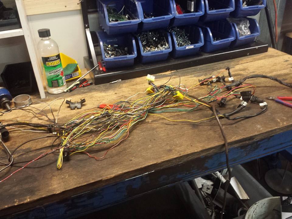
Old loom (TR Magna I think - I didn't cut it much originally, just bunched and looped it in the conduit)

For some reason I take pleasure doing this

Was going to machine up a 36-1 replacement for this wheel but the teeth may have been to narrow for the sensor to work. I just ended up using it as is although Megasquirt recommend more teeth for accuracy. I thougt about putting a wheel on the back of the cam where the magna water pump was driven but have decided a toothed wheel on the crank will be the way i eventually go so as to take any timing chain slack/stretch out of the equation.

Old loom (TR Magna I think - I didn't cut it much originally, just bunched and looped it in the conduit)
For some reason I take pleasure doing this
Was going to machine up a 36-1 replacement for this wheel but the teeth may have been to narrow for the sensor to work. I just ended up using it as is although Megasquirt recommend more teeth for accuracy. I thougt about putting a wheel on the back of the cam where the magna water pump was driven but have decided a toothed wheel on the crank will be the way i eventually go so as to take any timing chain slack/stretch out of the equation.
-
Sigmaproject
- Posts: 1143
- Joined: Sun Mar 22, 2009 7:11 am
- Location: Maitland NSW
Re: Matt's Red GN
This is the part where I get totally screwed. I have all of the gear ready to go..but I just know that if I get it wrong and the wagon does not run,it will be doomed to the scrap yard.
Re: Matt's Red GN
Never give up! The beauty of wire is that you can cut or join it without a lot of tools or skill; It's not like many other car crafts where if you stuff up it is game over! Often any problems you come across will be somthing stupid like hooking the spark leads in incorrect pairs or missing a vacuum line. I had made both mistakes but now the car is running!
Re: Matt's Red GN
I had a problem with the original EFI conversion where my idle was always strange. I found later that the idle stepper was stuffed (Open stepper coil). I just blanked it off as it was a huge piece of equipment that looked ugly anyway. I am going to see how I go with no idle control, then maybe add a PWM valve to there the pollution lines used to go in the intake if I have major problems. I suspect that with no power steering or airconditioning I will have no real problems. (I can set the power steering motor to only come on if the RPM is above 600 or some other rule)

Some of the initial MS3x wiring. One of the worst parts about these ECUs is the dicky connectors.

As I was recycling old looms, my workshop was quite a mess by this stage. Note tunerstudio running on a nice large screen via bluetooth.

I moved the factory relays out of the way and installed this fusebox from jaycar (I already had it from the previous EFI build) It is driven from the fuel pump relay. You can also see the negative post and positive post/bobbin. My theory is with a common earth post like that, earth loops should be avoided.

Some of the initial MS3x wiring. One of the worst parts about these ECUs is the dicky connectors.
As I was recycling old looms, my workshop was quite a mess by this stage. Note tunerstudio running on a nice large screen via bluetooth.
I moved the factory relays out of the way and installed this fusebox from jaycar (I already had it from the previous EFI build) It is driven from the fuel pump relay. You can also see the negative post and positive post/bobbin. My theory is with a common earth post like that, earth loops should be avoided.
Re: Matt's Red GN
Throttle cable is just a bicycle brake one. I dilled a small hole in the throttle pulley and used a nut/bolt with a hole drilled in it to put the end stopper on.

I've seen cars with the gauges mounted on the bonnet. I thought I'd take it one step further and mount the ECU on the windscreen.

Decided I wanted the injector wiring to be little more hidden.

I put a RIV-NUT into the place where the relays go and created a common earth stud. Hopefully this will mean no earth loops.

Coils working. I have been told to touch them, lick them, even put a rat on them. I don't suggest trying any of this!

Wideband unit is working! Unusual as I had no end of trouble with it in the S13. As with most of my work I have opted for the build it option here. Also means no wanky gauge to have to mount on the dash.

Nearly started! I later found that all was wrong was the plugs paired 1-3 2-4 instead of 1-4 2-3

Wired and mounted the S13 ignition barrel. Works pretty good except that once the engine is running, it will not stop when you remove the key. I have not been able to figure this out yet.


Got it started, forgot to hook up the vacuum line to the ECU. Smokeshow.
I've seen cars with the gauges mounted on the bonnet. I thought I'd take it one step further and mount the ECU on the windscreen.
Decided I wanted the injector wiring to be little more hidden.
I put a RIV-NUT into the place where the relays go and created a common earth stud. Hopefully this will mean no earth loops.
Coils working. I have been told to touch them, lick them, even put a rat on them. I don't suggest trying any of this!
Wideband unit is working! Unusual as I had no end of trouble with it in the S13. As with most of my work I have opted for the build it option here. Also means no wanky gauge to have to mount on the dash.
Nearly started! I later found that all was wrong was the plugs paired 1-3 2-4 instead of 1-4 2-3
Wired and mounted the S13 ignition barrel. Works pretty good except that once the engine is running, it will not stop when you remove the key. I have not been able to figure this out yet.
Got it started, forgot to hook up the vacuum line to the ECU. Smokeshow.
Re: Matt's Red GN
Whoops - no edit function !? THis is meant to be the last pic

Re: Matt's Red GN
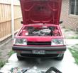
It lives!
I have had taken it for a drive and got the tune working OK! Quite a lot of power and only on 6PSI. I don't think i should up the boost as the motor is stock compression. Handling is absolutely insane - steering feel is amazing. Turn in is hard and the stock seats do not do a good job of holding you in them. Brakes are mediocre but working - i think i need to bleed them again.
Problems I have are that is it loud - extremely loud. Also the exhaust hits on the body in various cornering and idling conditions making it even worse. I think I need to adjust the angles and possibly notch the dump pipe a little as it hits the steering shaft on left hand corners.
Another problem is leaking sump. For the moment I will put up with it and keep checking the oil, but hopefully I can fix it by lowering the crossmember rather than motor out.
Boost feels almost immediate. I'm sure it's not, but it is far superior to my RB20 in terms of lag.
I've recently put a heavy duty clutch in but I'm not sure if its that slipping on the crappy rear tyres in 3rd and 4th gear.
I have come to the conclusion that the 4g54 is definitely an engine worth playing with.
Re: Matt's Red GN
(Catch up posts)
Had to drastically modify the bonnet latch. Still not sitting right. Also incorporated a piece of rope as a secondary restraint as i had to remove the factory safety latch.


Intercooler hidden nicely.

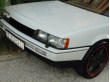
Pushed it back for the front profile pic as requested

The wiring for the S13 wiper control was not directly compatible with the Sigma wiring so i just cut up the sigma stalk and jammed it in with self tappers. The light control was sort of compatible and worked with a bit of trickery. (couple of not connected, a couple paired up)

I was fairly happy with how the loom came out. Far better than previous efforts. Also nearly all recycled wire.

It's all pretty tidy when installed. The fusebox is a bit of a ratnest, but is easy to diagnose the way it is configured. I tried hidin the wires by going underneath the hydraulic unit but was way too hard to work on.

I had some scrap stainless from some old thermal printers so I recycled it for a heat shield, not pretty, but I'm sure it will work and could be made to look better later on. Maybe some silicon hose split and pressed along the top edge and round the corners


(still haven't caught up)
Had to drastically modify the bonnet latch. Still not sitting right. Also incorporated a piece of rope as a secondary restraint as i had to remove the factory safety latch.
Intercooler hidden nicely.
Pushed it back for the front profile pic as requested
The wiring for the S13 wiper control was not directly compatible with the Sigma wiring so i just cut up the sigma stalk and jammed it in with self tappers. The light control was sort of compatible and worked with a bit of trickery. (couple of not connected, a couple paired up)
I was fairly happy with how the loom came out. Far better than previous efforts. Also nearly all recycled wire.
It's all pretty tidy when installed. The fusebox is a bit of a ratnest, but is easy to diagnose the way it is configured. I tried hidin the wires by going underneath the hydraulic unit but was way too hard to work on.
I had some scrap stainless from some old thermal printers so I recycled it for a heat shield, not pretty, but I'm sure it will work and could be made to look better later on. Maybe some silicon hose split and pressed along the top edge and round the corners
(still haven't caught up)